Thursday, 12 May 2016

Line following

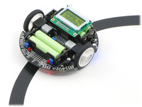
If you're up for a programming challenge the 3Pi robot is capable of following lines (and they can do it really fast!). Luckily Anibit includes an example you can try:


Its a lot to understand, but if you want to jump ahead a bit you can start by loading the following XML file (these bits do calibration and battery display so you don't need to worry about them too much). 


Start with an infinite repeat:

Each repeat, do the following:

Start by reading the sensor:

(display is if you want to)

Then make a decision based on the sensor
Greater than 2000 means the line is on the left, less than means the line is on the right

Here's a diagram to explain what the sensor gives you:

The simplest thing is to turn on the motors based on which side of the line you are on:


If you want to move more smoothly you can try making even more decisions:


Wednesday, 11 May 2016

Checking the 3Pi's batteries

This code can be loaded into Arduino to check the batteries on the 3Pi:

#include <Pololu3pi.h>
#include <PololuQTRSensors.h>
#include <OrangutanLCD.h>
#include <OrangutanAnalog.h>
OrangutanLCD lcd;
OrangutanAnalog analog;

void setup()
{
  Pololu3pi::init();
  analog.setMode(MODE_10_BIT);
}


void loop()
{
  lcd.clear();
  lcd.print("Battery ");
  lcd.gotoXY(0,1);
  lcd.print((long)(100.0 * (analog.readBatteryMillivolts_3pi() - 3000.0) / (4000.0)));
  lcd.print('%');
  delay(500);
}

Monday, 9 May 2016

Getting started with 3Pi


The 3Pis is a small completed robot with all the parts from previous modules


It has a buzzer, motors, line/distance sensors and LEDs.

Top view:


Bottom View:


The easiest way to program the 3Pi is using Arduino and Anibit's free graphical programming tool. To set these things up see the post about 3Pi software. The installable Anibit program might be a bit trickier to set up and only works on Windows. Another way to use it is to copy your code from The Anibit online tool.

To get started lets make the robot move forward and backward a few times, we'll also display the current battery level in millivolts (5 volts = 5000 millivolts).

Note: we need to display the battery level. 
If you program on a battery level near or below 5000mV you can destroy your robot.

Here are the blocks we will use:


  • Math is where you get number blocks to plug into other slots.
  • From Arduino the Setup block is similar to Ardublock: it runs the code inside just once
  • From Motors the Set Motors block sets the power level of the motors between 0 and 255. Faster speeds will drain your batteries. If you're moving you'll need a Delay to tell the robot how long to keep moving (in milliseconds: 1000 * second).
  • From Display you can get blocks to put words on the robot's screen. Try adding the battery level from 3Pi Analog.
  • If you turn on the motors, don't forget to turn them off by setting them back to 0!
When you have the blocks arranged correctly you must switch to the top Arduino tab and copy your code. (Shortcut: use <Ctrl>+<A> then <Ctrl>+<C> to copy it all).

Open up the regular Arduino program and paste in your code (Shortcut: use <Ctrl>+<V> to paste).


Make sure you have selected:
  • Tools > Board > Pololu ... 3Pi robot w/ ATmega328P
  • COM4 (if this doesn't work ask somebody for help- you have to check 'devmgmt.msc' to find the right one)
  • Programmer > Pololu USB  AVR Programmer
If you're all set turn on your robot and hit upload!


Sunday, 8 May 2016

Day 1

11: Making Robots Move


Wiring

How it works

HG7881 (L9110) Dual Channel Motor Driver Module Connector
PinDescription
B-IAMotor B Input A (IA)
B-IBMotor B Input B (IB)
GNDGround
VCCOperating Voltage 2.5-12V
A-IAMotor A Input A (IA)
A-IBMotor A Input B (IB)

InputOutput
IAIBOAIBDescription
LLLLOff
HLHLForward
LHLHReverse
HHHHOff
'

Code

Basic code to drive forward

Extensions

  • Can you make it go forward, then backward?
  • How about turning?
  • Can you make it drive forward if the distance sensor reads 'LOW'?
  • If you have 2 distance sensors can you make it turn left for one, then right for the other? This is how you follow a line!


10: Distance and line sensing


Using the same code which reads from the joystick we can read distance. Reflecting light, or reflecting sound can be used to measure distance:


A reflectance sensor can be connected as follows:


9: Buzzer

Background Information

By precisely modulating a pin, the Digital Sandbox can create electronic waves which, when routed through a loudspeaker, can produce a musical tone. We can program the Sandbox to control two characteristics of musical tone: pitch and duration.
A tone’s pitch is what we perceive when we think of a note as being very high (screams, forks scratching plates, etc.) versus very low (like earth-rumbling bass). The pitch of a tone is very closely related to the frequency played through a speaker. If we toggle a pin from HIGH-to-LOW then LOW-to-HIGH 440 times per second, for example, it produces a 440 Hz (hertz) frequency - a “middle A” pitch. Humans can hear frequencies ranging from 20 (low-pitch, bass) to 20,000 Hz (high-pitch, “ow, my ears”).
We can also program the duration of a tone - the length of time a pitch is played. In our program we’ll use the delay function to set the duration. Playing a tone with the Sandbox is very easy. Just give it a pitch and it’ll start toggling the output pin for you. Much like analog output, you can set it and forget it; the tone won’t stop playing until you tell it to.

Hardware

The joystick should be connected as before. The buzzer is connected as follows:


Code Components


This program introduces the Tone and No Tone block.
  • Tone: This block takes two inputs: a pin number and a frequency. The pin number can be any digital pin, but in this case we’ll use 10. Frequency can be anything from 31 Hz to the extent of your audible range.

    A tone initiated by the Tone block will go on and on until you call a No Tone block. No Tone simply halts a pin from playing a tone. Both of these blocks can be found under the Utilities bin.
  • Map: This handy function maps a value from one range to another. In the example above, we’re taking a value (the output from the joystick) between zero and 60, and mapping that to a range from 440 to 880. So an analog reading of zero becomes 440, and a reading of 60 becomes 880, anything in between is relative to those two ranges. The map function can be especially useful in mapping an analog input (0-1023) to an output (0-255).

Further Explorations

If you have some sheet music, you can convert it to individual notes, made of frequencies and durations using the following table: