Sunday, 8 May 2016

2: Multi-Blink

Large arrays of LEDs are often used to create massive outdoor signs and animations because they’re both bright and efficient. While we don’t have the millions of LED pixels that a display in Times Square might have, we can still create some fun patterns.

Background Information

In this experiment we explore the subject of pins. Each LED (as well as the other inputs and outputs) is connected to a specific pin on the microcontroller.
Pins are all uniquely numbered, and each input or output component on the Arduino is labeled with the pin number it’s connected to – that’s the (Digital) 1, 23(Analog) A1, etc. lettering next to each pin.
Every pin can be separately controlled; for instance pin 4 can be set HIGH at the same time pin 5 is set LOW. Some pins (as we’ll later discover) have special powers, but every pin is at least able to accomplish digital input and output.
We started with a single LED, but we can add our own:

Code Components

Whoa! Block explosion! This experiment calls for a lot of blocks:

Instead of introducing a new block, we’ll be adjusting the value of Set Digital Pin’s top pin - the pin number. This value specifies which of the Sandbox’s pins we’ll be toggling.

Do This

In our unfinished example, the blocks are all arranged in groups of four. Each group begins by setting a pin HIGH, then delays for a second and sets it back to LOW. Notice that each group toggles a different pin, ranging from pin 9 to pin 11. Stack the groups-of-four on top of each other in the loop, then upload and enjoy the exciting animation.
If the LED change is too slow for you, try adjusting the delays to make it faster, or perhaps you want to change the pins to adjust the order of the blinks.

Further Explorations

  • Try adding more blocks to create slicker patterns. 
  • Try turning on more than one LED at a time. Turn them all on (and shield your eyes)!


1: Exploring Blink

Now, we didn’t exactly cheat in experiment zero, but the Blink block was a bit of a shortcut. What if you wanted to speed up the blinking? Or change how long it’s on versus how long it’s off? Or even blink something other than that wimpy little LED?

Background Information

This experiment digs into the anatomy of the Blink block. We can customize an LED blink with a combination of two blocks – Set Digital Pin and Delay Milliseconds.
This experiment introduces the concept of digital output. We call the Sandbox’s LEDs “outputs,” because it’s an effect that the board produces.
The term “digital” means that the output can only take one of two states: ON or OFF. We may also refer to those two opposing states as HIGH/LOW or 1/0. When an output connected to an LED is HIGH, the LED turns on. When the output is LOW, the LED turns off.

Code Components

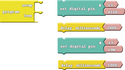
Here is the set of blocks we’ll use to create this drawing:
alt text
Aside from the Program block (which you should include in every drawing), there are two new blocks to be added:
  • Set Digital Pin: This block sets an output to either HIGH or LOW, so it can be used to turn the LED on or off. Find this block under the Pins bin. When you drag this block over, it includes a pair of pink blocks containing “13” and “HIGH.” Let’s only concern ourselves with the bottom pink block for now.
    • HIGH/LOW block: If you mouse over this block, a drop-down arrow will appear. Click the arrow and you can change the value of the block to either “HIGH” or “LOW.” This determines which of the two states you’re setting the digital output to.
  • Delay Milliseconds: The Digital Sandbox runs code so fast that sometimes we need to slow it down with a delay. This block will halt the Sandbox from doing anything for a specified number of milliseconds. There are 1000 milliseconds (ms) in a second, so delaying for 1000ms will stop for one second. Find this block under the Control bin.

Do This

Organize and snap together the Set Digital Pin and Delay Milliseconds blocks so they alternate – teal, yellow, teal, yellow. Then put the group of four blocks in the loop section of the Program block. Then Upload the code.
You should see a very familiar sight. But this time you have control over the blink rate! Adjust the value in the Delay Milliseconds block(s). What happens if you make the delays shorter? What happens if the two delays are not for the same amount of time?
The Leonardo operates at 8MHz – there’s a clock in there that ticks eight million times per second. That means it can run millions of lines of code per second. Without any delays in the program, the digital output would flick on and off so fast you wouldn’t be able to tell if it’s actually on or off.

Further Explorations

  • How short can you make the delays and still notice a blink? Ten milliseconds? One millisecond?
  • What happens if you take the Delay Milliseconds block out of the program?
  • While digging around for the Delay Milliseconds block, you may have discovered a Delay Microseconds block as well. What happens if you swap that in?

0: Setup, Loop, and Blink

[This is straight up stolen from https://learn.sparkfun.com/tutorials/digital-sandbox-experiment-guide/0-setup-loop-and-blink, in order to modify it for the different hardware modules]

When faced with a new platform, a coder’s first task is to write a “Hello, world” program. Usually a “Hello, world” program actually prints those comforting words on a screen. The Digital Sandbox doesn’t give us a screen to print words on, but we do have LEDs! Wonderful, blinky, bright, shiny LEDs. Instead of printing words, let’s blink an LED to say “Hello, world.”

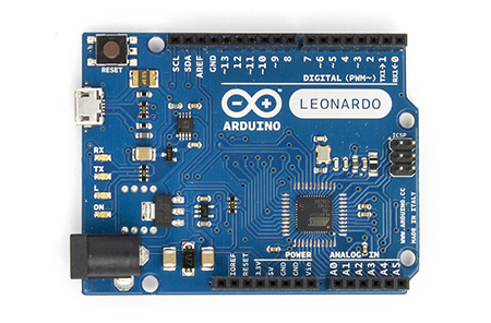
The Arduino Leonardo, as with most Arduinos has a special pin connected to an LED. This pin is 'digital pin 13'


Code Components

This code drawing requires two blocks (well, sort of three):

  • Program: This block is required for every single ArduBlock drawing ever! You can only have one per drawing.Program always has two slots for blocks – one named “setup” and another named “loop.” Find this block under the Control bin.
  • Blink: Find this block under the Pins bin. This block “blinks” a pin on the Digital Sandbox. The Blink block actually gives you two blocks for the price of one! It also includes a pink block with the number 13 inside it. Leave that block alone for now, we’ll discover its use in later experiments.

Do This

With this pair of blocks, there are only two functional drawings we can create. You can either stick the Blink block under the setup section of program, or under the loop section.

Try sticking the Blink block under setup, then click Upload to Arduino.
Upload to Arduino
Keep your eyes glued to the Digital Sandbox as the code uploads. You’ll see the red and green RX and TX LEDs blink like crazy as code is sent from computer to Sandbox. Pay extra close attention to what happens after the red and green LEDs do their dance. Do you notice anything?
Now move the Blink block from setup to loop, and do the Upload to Arduino jig again. Notice anything different?

Every Arduino program requires two functions always be present: setup and loop. From the names of these functions, it should be pretty clear what their job is.
Setup runs once, at the very beginning of the program. Its purpose is usually to set the platform up for the rest of its lifecycle (until the Sandbox is reset, or loses power). As we continue on with these experiments, you’ll have a greater understanding of what kind of things need to be set up in advance.
If setup sets the Sandbox up, Loop must…loop. Code in this block will execute sequentially and endlessly. Once we get to the bottom of loop, we jump right back up to the top and do it all over again. This looping will continue until you either reset or remove power.

Further Explorations

  • What happens when you press the reset button?
  • What happens if there’s nothing in either setup or loop (move the Blink block out)?
  • What happens if you add a second Blink block to the drawing? Regardless of where you put it, can you discern which of your Blink blocks is being executed?
  • What do you think the 13 inside the Blink block is for?

Getting started with Ardublock

[This is straight up stolen from https://learn.sparkfun.com/tutorials/alternative-arduino-interfaces/ardublock, in order to modify it for the different hardware modules]

  1. Start Arduino – Or restart it if it was open.
  2. Select the Board and Serial Port – Just as you would if you were using Arduino, make your board and serial port selections from the “Tools” menu.
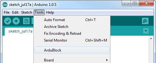
  3. Open ArduBlock – Run ArduBlock by clicking Tools > ArduBlock. If you don’t see an entry for ArduBlock here, double-check to make sure your directories are all correctly typed and cased.

ArduBlock works hand-in-hand with the Arduino IDE – it relies on the IDE being open in the background, so don’t close the Arduino window!

Using ArduBlock

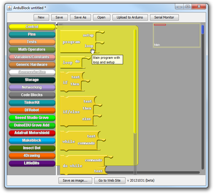
The ArduBlock window is split into two halves. On the left there are “bins”, which store every possible block you can add to your sketch. The blank, gray slate to the right of that is where you “draw” your sketch. To add a block to your sketch, simply drag it from the bin into the blank, gray area.
To begin, every ArduBlock sketch requires a Program block, which you can find in the “Control” bin. The Program block defines the setup and loop functions that every Arduino program requires.
Ardublock program location
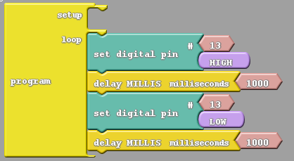
From there, you can drag more Blocks over, snapping them into either the loop or setup sections. Here, try making a blink program. The set digital pin blocks, which effect a digital output (analogous to Arduino’sdigitalWrite function), are found under the “Pins” bin. The delay milliseconds block, found under “Control”, is analogous to a delay Arduino function.
Ardublock blink program
Then click Upload to Arduino to send your drawing off to your Arduino board. You can ALT+TAB back over to the Arduino window to check your code upload status.
Upload program
After you’ve successfully uploaded your first sketch, continue to play around and explore the contents of the other bins!

ArduBlock Tips & Tricks

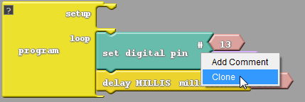
You can clone blocks, or groups of blocks, by right clicking and selecting “Clone”. Everything from the block you right-clicked to the bottom of that “group” will be copied and pasted into the top-left corner of the window. This is a hugetimesaver for bigger drawings.
alt text
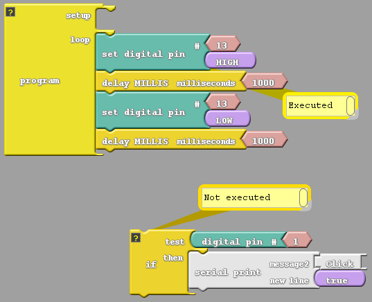
You can temporarily remove code from your sketch by dragging it out of the entirety of the “Program” block. Anything not connected to the main Program block will be ignored when your code is compiled. This is a great debugging tool – you can remove a block of code from program execution, while not actually deleting it, much like commenting out code.
alt text
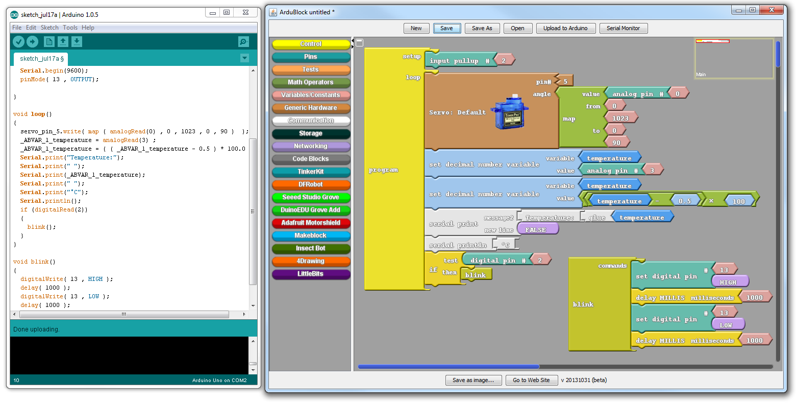
Finally, if you peek back over at the Arduino window, after you’ve uploaded an ArduBlock drawing, you may notice something different. To create your code, the ArduBlock program simply parses your blocks and spits the equivalent Arduino code over into the Arduino window.
alt text
This becomes a great learning tool if you’re interested in transitioning from graphical programming to text.

Saturday, 7 May 2016

3pi Software


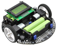
To use the 3Pi robots with Arduino install the Pololu 3Pi Drivers, Pololu Arduino Add-on and Anibit Graphical Robot Programming Software. If you do not have Arduino installed see the other tutorial.

Arduino Ardublock Software


To get started with a regular Arduino, like a Leonardo, download Arduino (hit the download arrow at top) and Ardublock.

Extract Arduino to your desktop and run Arduino.exe

Go to File > Preferences and find "sketchbook location".


  • In Windows, it’s by default “Documents\Arduino” under user’s home directory


  • In Mac, it’s by default “Documents/Arduino” under user’s home directory
  • In Linux, it’s by default “sketchbook” under user’s home directory


  • Close Arduino and copy ardublock-beta-20140702.jar to tools/ArduBlockTool/tool/ardublock-beta-20140702.jar under "Sketchbook location"

    If the user is "abu":
    • In Mac, /Users/abu/Documents/Arduino/tools/ArduBlockTool/tool/ardublock-beta-20140702.jar
    • In Linux, /home/abu/sketchbook/tools/ArduBlockTool/tool/ardublock-beta-20140702.jar
    • In Windows, C:\Users\abu\Documents\Arduino\tools\ArduBlockTool\tool\ardublock-beta-20140702.jar

    * Be careful, the name of folder “ArduBlockTool” under tools folder is case sensitive.

    Plug in your Arduino Leonardo. It should install drivers automatically. 

    If it does not and you are on Windows launch the device manager (hit Picture of the Windows logo key+R and run devmmt.msc).

    The Arduino should show up as 'Other Devices>COM5' or 'Ports (COM and LPT) > Arduino Leonardo (COM5) - note that you may see a different COM number, try to remember it.

    Right click and 'Update Driver Software', browse to the location of your Arduino install (ex: C:\Users\User\Desktop\arduino-1.6.8\drivers) and allow it to install (even if it says driver is unverified).

    Restart Arduino, ArduBlock should be found under the Tools menu:

    Untitled

    Under 'Tools > Board' select 'Arduino Leonardo', under 'Tools > (Serial) Port' select 'COM5' or whatever number you noted above in DeviceManager.

    To test it out build the following in Ardublock and hit upload (how it works will be explained in another tutorial)


    You could also test your settings by selecting the Blink example from the Arduino menu and hitting upload:


    If it's working you should see the on board LED flashing, changing the delay will change the speed of flashing.

    For details check out these references:
    • Current Arduino software: https://www.arduino.cc/en/Main/Software
    • Pololu add ons for Arduino (as included in the modified download at top): https://www.pololu.com/docs/0J17/3
    • Ardublock download and setup: http://blog.ardublock.com/engetting-started-ardublockzhardublock/
    • Leonardo driver info: http://www.kmpelectronics.eu/en-us/questionsandanswers/installingdriversforarduinoleonardo.aspx