Sunday, 8 May 2016

8: Analog Input and Serial Communication

Digital inputs, like a button, only allow for two input values: HIGH or LOW. But what about the in-betweens? When you turn the volume up on your stereo, you’re not forced to pick between mute and “OMG MY EARS.” For volume control and other “finely-tuned” settings, we need analog inputs.

Background Information

Serial communication is a form of data transmission where we can send a string of 1’s and 0’s between two devices and actually form a set of characters. So 01101000 01100101 01101100 01101100 01101111 00101100 00100000 01110111 01101111 01110010 01101100 01100100 becomes “Hello, world.”
With serial, we can send actual text from the Arduino and display it on our computer using the Serial Monitor.
Analog inputs are components that put data into a system with a range of more than two values. On the Arduino, analog inputs can produce a value anywhere between zero and 1023 (1024 total values). The value produced by an analog input is proportional to the voltage it produces. If an analog component reads a value of zero, the voltage is 0V. If the output value is 1023, then the voltage is 5V. An analog reading of 512 is about 2.5V, and so on.
A special component inside the Arduino's microcontroller called an analog-to-digital converter (ADC) is able to convert that range of input voltages to a discrete number. This is a special circuit that most pins on the Arduino don’t have. It’s so special that the ADC pins are labeled with a preceding ‘A’. The analog sensors on the board are labeled as “A0”, “A1”, “A2” and “A3.”
Many electronic components produce analog output, the most common of which is a potentiometer. “Pots” come in a variety of shapes and sizes. Rotary pots are very commonly used to adjust the volume on a stereo. Slide potentiometers are often seen adjusting sound levels on mixing boards. Joysticks use 2 rotary pots: one for side to side (VRx), one for up/down (VRy).

A joystick can be connected as follows:

Code Components
alt text
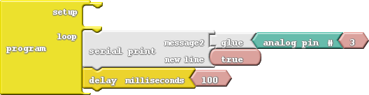
There are three new blocks this time, both of them shaded white and located under the communication bin:
  • Serial Print: This block takes two parameters. At the top, place the message you want to print. You can put anything you want into the message block (even spaces!). If you want to add a variable or number, you’ll need to add some glue. The bottom snap of Serial Print determines if a new line is printed after the message. Usually you’ll want this to be set to true.
  • Glue: Glue blocks allow you to print values like variables or numbers - anything that isn’t a message you’ve written in. If you want to print a variable, you’ll need to add a glue block between the variable and the Serial Print block. There are three different kinds of glue blocks, each with a different snap shape on the right. This time we’ll use the block with a wedge (<) termination.
  • Analog Pin #: Like the Digital Pin block, this block reads in the value of an input. But, instead of producing either true or false (1/0, HIGH/LOW), this block produces a number between zero and 1024. The pink block snapped to the right of this one indicates which analog pin should be read.

Do This

To print a variable, we need to “glue” it to the Serial Print block with a wedge-shaped glue piece. Make your drawing match the one above.
With that, upload the sketch to your Arduino. Then, to view the serial prints, click on the Serial Monitor button up top.

alt text
You’ll see your message printed.
Every 100ms an analog input value should be printed. Move the analog slider to adjust the value. Can you make the output zero? 1023? 512? Take note of which slide pot position relates to which value.

Further Explorations

  • Can you make the slider control the LEDs? You could slide the white LEDs back and forth, or try controlling the brightness of the RGB LEDs with the slider.
  • Why are there only 1024 output values? Why not an even 1000? (Hint: 210.)

7: If This Then That

Fading from the last experiment was working just fine until we got to the maximum brightness level of 255. What happens then is a mystery known only to the compiler (and you, once you learn a little something about data types). What if we added “catch” to force that fade variable to reset when it hits a certain value?

Background Information

This experiment introduces the if statement, one of the most fundamental programming structures. Not only are ifstatements important for computers, they also rule most of the decisions we make in our lives: If it’s cloudy outside,then pack your umbrella. If you’re hungry, then make a sandwich. Like us, computers use if statements to make choices.
An if statement requires two components to be complete: a condition and a consequence. A condition is a value or mathematical operation that evaluates to either true or falseIf the condition evaluates to true, then the consequence is executed. The consequence can be a code block of any size - one block or hundreds of blocks.
If the condition in the if statement is false, then the consequence is skipped, and the program starts running the code following the if block.

Code Components

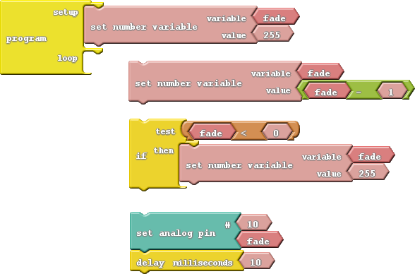
Here are the blocks required to limit the fade value of our LED.
alt text
There are two new blocks to mention here:
  • If: The star of this experiment can be found under the Control bin. The If block requires at least two blocks to be snapped into it: the conditional and the consequence. In this case, the consequence is just a single block -Set Number Variable. The conditional part of the if block is a logical operator block.
  • Logical Operator: Logical operators are symbols which operate on one or two values and evaluate to either true or false, which makes them perfectly suited for the if statement conditional! In this case we’ll be using theless than (<) operator. If the value to the left of the < symbol is less than the value on the right, then the operator is true. If the left is not less than (either greater than or equal to), then the condition will evaluate to false.

Do This

In this sketch, we want the blue LED to progressively go from super bright to off, and repeat that cycle endlessly. We’ll use a variable called fade to keep track of the analog output value. At the very beginning of each loop, we’ll subtract 1 from the fade variable.
Then, after subtracting from fade, we need to use an if statement to make sure it’s not out of bounds. The ifstatement in this sketch states that if fade is less than 0 (that would mean it’s a negative number), then set fadeto 255.
Finally, once we’ve generated our fade value, we can set pin 10 (or pick another LED if you please) to that analog output value.
Now upload and enjoy a nice, controlled fade.

Further Explorations

  • Can you make the fade work the other way? Start at 0, fade up to 255, and then go back to 0. (Hint: You’ll need to flip the logical operator around.)
  • Make it even smoother! Can you make it fade smoothly up and smoothly down in the same sketch? From 0 to 255, then 255 to 0, then 0 to 255, then back again.

6: Number Storage with Variables

The herky-jerky fading from experiment four accomplished the task, but just think of all the values we were missing! How do we make the LED fade smoothly? You can whip out 256 minutely different Set analog pin blocks, or you can reduce it to one, using variables.

Background Information

Variables are like storage containers for numbers. We can put any number in a variable, and either recall it and put it to use, or manipulate it to change the value it stores. Anywhere you stick a literal number (like “0” or “255”) you can instead use a variable.
There are a few rules when it comes to creating a variable. They can be any word, but they must begin with a letter, and they can’t have spaces (use “_” instead). They are case sensitive, so a variable named “fade” isn’t the same variable as “Fade.” Try to keep variables short, but use descriptive words to keep your code legible.

Code Components

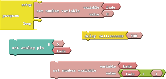
Thanks to variables, here are all the blocks we need to create a smooth fade:
(note: change pin 5 to one connected to an LED, like 9,10,11,13)
alt text
There are a few new blocks to familiarize yourself with this time:
  • Number Variable Name: These blocks are about the same size and shape as the literal number blocks we’ve been using. But, instead of writing a number in these blocks, you type in the name for your variable (make sure it’s spelled the same in every place you want to reference it). You can find this block under the Variables/Constants bin on the left.
  • Set Number Variable: This block, also found under the Variables/Constants bin, is used to set a variable to a specific value. Two blocks snap to this one – a variable name on top, and the value you want to set that variable to on the bottom. The value can be a literal number, another variable, or the result of a mathematical operator.
  • Math operator block: If you click on the Math Operators bin, and look at the first four entries, you should see some very familiar symbols: +, −, ×, and ÷. These math operators can be used to do math on a pair of variables or numbers, or a combination of the two.

Do This

Add the first Set Variable Number block, which will include a blank variable and a value. Click into the number variable name and write “fade” into it. The “fade” variable will keep track of the the brightness of our LED. The Set Variable Number block in the setup area of the program should set the “fade” variable to zero.
You should be plenty familiar with Set Analog Pin and Delay Milliseconds; grab those blocks and stick them in the loopin either order.
We’ll need to throw away the value block that comes with Set Analog Pin (drag it over to the left side of the window) and replace it with a variable. To add a variable to your sketch, drag over the Number Variable Name block and type your variable’s name into it. Alternatively, once you’ve made one variable, you can right-click it and clone it to get more of the “fade” variables you’ll need.
Finally, add another Set Number Variable block, and replace the 0 value it includes with a + operator. Modify it so it adds a 1 to “fade,” and plug it into the value part of the Set Number Variable block. Then stick that block group at the end of the loop.
Whew! Let’s see what all that work was for by uploading the drawing. The LED on pin 5 should satisfyingly and smoothly flow from fully off to fully on.

Further Explorations

  • Does it matter what order you have the loop blocks in?
  • Can you make other LEDs fade? How about more than one fading at the same time?
  • Can you make the LED fade from HIGH to LOW? (Hint: You may need to change the setup value of “fade,” and change the + to a −.)

5: Color Mixing


By combining analog output with an RGB LED, we can mix varying levels of red, green and blue to create a rainbow of colors!

Background Information

In art class you probably learned about primary colors and how you can mix them to produce any other color. While the artsy primary colors you might be familiar with are red, yellow and blue, in electronics (and programming in general) our primary colors are red, green and blue.

Additive color mixing seen in light


Subtractive color mixing as seen in paint

By selecting different analog levels for our primary colors, we can mix them to create any other color we want. Need yellow? Mix green and red. Purple? Red and blue. In this experiment we’ll combine everything we’ve learned about analog output to create any color!

Code Components

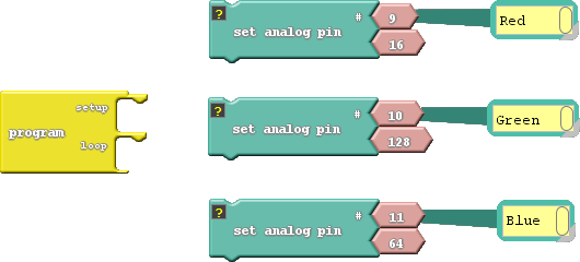
For the most basic RGB color-mixing sketch, this is all we need:
alt text
In the example, we added comments to each of the Set Analog Pin blocks. Comments have no effect on the actual code, but they do help make the code more readable to you or others. With those blocks commented, we don’t have to look back at the board to remember which pins go to which colors.
You can add comments by right-clicking on a block, and selecting “Add Comment”. Show or hide comments by clicking the “?”.

Do This

Stack those three Set Analog Pins on top of each other, in either the setup or the loop. This will set red’s value to 16, green to 255, and blue to 128. What color do you think it’ll make? Upload to find out! (If it’s hard to tell what the color is, put a piece of paper over the RGB LED.)
Play with the analog values to make your own colors. How about purple, or orange, or salmon? You can take it even further by adding delays, and blinking different colors to make animations.

Further Explorations

  • Mix the colors to make your favorite color. Or, if your favorite color is red, green or blue, try making your least favorite color.
  • Make a stop light blink from green, to yellow, to red and repeat.

4: Dimming (the Easy Way)

Manual PWM is hard, and it doesn’t leave room for anything else in the program. Why can’t we offload that chore to the microcontroller? It’s smart enough for that…right?

Background Information

PWM is such a popular tool many microcontrollers implement special hardware so they can mindlessly toggle the pin while doing something else. We call this PWM-based output analog output.
Unlike digital outputs, which only have two possible values, analog outputs have a huge range of possible values. On the Arduino we can analog-ly output 256 different values. If we set an analog output to zero, that’s like setting a pin LOW, and 255 is like setting a pin HIGH, but all of the values in between produce an output that’s neither HIGH or LOW – it’s somewhere in between.
Analog output seems great – why wouldn’t you use it all the time? Unfortunately, not all pins have special PWM powers. Only pins 3, 5, 6, 9, 10, 11 and 13 are able to produce analog outputs.

Code Components

New block alert! While it may look similar, we’ll be using Set Analog Pin this time instead of its digital counterpart:

  • Set Analog Pin: This block looks a lot like the Set Digital Pin block. We still tell it which pin to control, but instead of a restrictive, digital output option, we get to choose any number between zero and 255 for the output. Find this block under the Pins bin.

Do This

Stack the blocks in the loop section. Order them so the analog values go from zero at the top to 255 at the bottom. Then upload away!
The LED on pin 5 should cycle through five different levels of brightness (including fully on and fully off). Remember that setting the analog output to zero turns the LED off, and 255 is like setting it to HIGH.
Try adding analog control of the pin 6 LED to the drawing. You can create the same effect from the last experiment, with just two lines of code (and you can execute other code while the LEDs remain in their dimmed state!).

Further Explorations

  • What’s the dimmest value you can set the LED and still see it on?
  • Why do you think there are 256 possible analog output values? That doesn’t seem like a very round number (hint: 28).

3: Dimming (the Hard Way)

Yikes! Some of those LEDs are blindingly bright! Is there any way to dim them? (Unless one of your hobbies is staring into the sun, we recommend putting a piece of paper over the LEDs in this experiment…or wear sunglasses.)

Background Information

Remember that the Arduino is fast. It can flick an LED on and off millions of times per second. What if we blinked the LED super fast, but also make it so the length of time the LED is off is more than the length of time it’s on? This is called pulse-width modulation (PWM), a tool with a variety of applications, including dimming the LEDs.
In this experiment we’ll explore PWM the hard way, by coding it in manually.

Code Components

We’ll use a similar set of blocks:

Take note of how long each delay is, and which pins are on/off in each group.

Do This

Stack the two group of threes on top of each other, in the loop section, and Upload.
After uploading, take a close look at the LEDs connected to pins 9 and 10. Can you spot a difference between the two? One LED should look dimmer in comparison to the other. That’s because one is set to be low 90% of the time, and on only 10%. It’s blinking on and off so fast that you can’t notice. But what the blinking is creating is a dimming effect.
What happens if you swap the two Delay Millisecond blocks? What if you change the values in each of the delay blocks (try to keep the sum of the delay times to around 10ms)?

Further Explorations

  • How long can you make the delays before you start noticing a blink?
  • What happens if you add something else to the loop section, like your animation from experiment two?

2: Multi-Blink

Large arrays of LEDs are often used to create massive outdoor signs and animations because they’re both bright and efficient. While we don’t have the millions of LED pixels that a display in Times Square might have, we can still create some fun patterns.

Background Information

In this experiment we explore the subject of pins. Each LED (as well as the other inputs and outputs) is connected to a specific pin on the microcontroller.
Pins are all uniquely numbered, and each input or output component on the Arduino is labeled with the pin number it’s connected to – that’s the (Digital) 1, 23(Analog) A1, etc. lettering next to each pin.
Every pin can be separately controlled; for instance pin 4 can be set HIGH at the same time pin 5 is set LOW. Some pins (as we’ll later discover) have special powers, but every pin is at least able to accomplish digital input and output.
We started with a single LED, but we can add our own:

Code Components

Whoa! Block explosion! This experiment calls for a lot of blocks:

Instead of introducing a new block, we’ll be adjusting the value of Set Digital Pin’s top pin - the pin number. This value specifies which of the Sandbox’s pins we’ll be toggling.

Do This

In our unfinished example, the blocks are all arranged in groups of four. Each group begins by setting a pin HIGH, then delays for a second and sets it back to LOW. Notice that each group toggles a different pin, ranging from pin 9 to pin 11. Stack the groups-of-four on top of each other in the loop, then upload and enjoy the exciting animation.
If the LED change is too slow for you, try adjusting the delays to make it faster, or perhaps you want to change the pins to adjust the order of the blinks.

Further Explorations

  • Try adding more blocks to create slicker patterns. 
  • Try turning on more than one LED at a time. Turn them all on (and shield your eyes)!